16.6 Basic Elements of Welding Symbols
Cameron Kjeldgaard
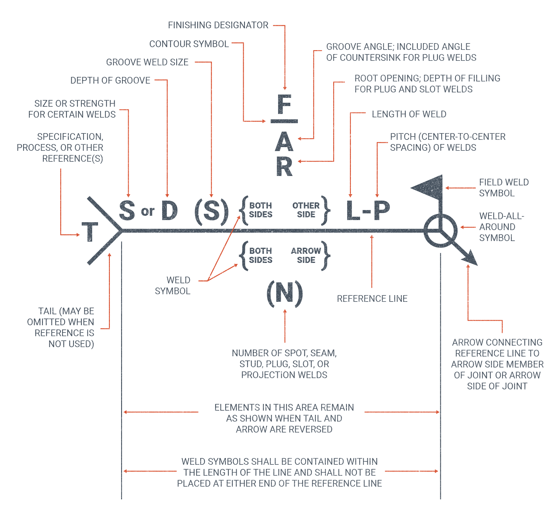
If an engineer or designer would like welding to be carried out on a project, they need a way to communicate that to those who are doing the welding via the blueprint. This is done with a welding symbol.
Welding can require a lot of specific information: for example, the type and size of the weld, the required weld groove preparation, the extent and location of the weld, and more. Welding symbols provide a space-saving method for conveying all this information and more. There is a certain amount of explanation required to interpret welding symbols properly. That is what this section covers.
Before proceeding, it is highly recommended that you read Chapter 15 on weld identification first, as the information covered is necessary to understand the types of welds and weld dimensions discussed in the following sections.
Reference Lines, Arrows, and Tails
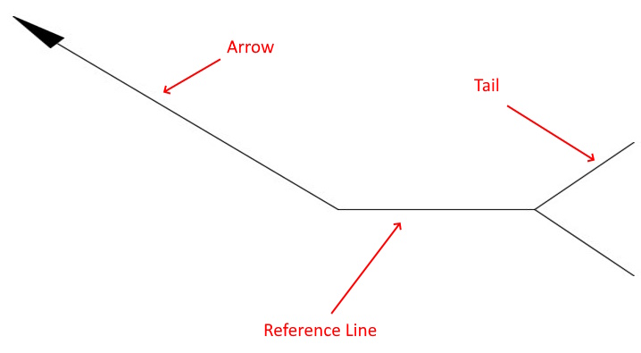
In welding symbols, the arrow serves the same function as a leader line: the arrow points to the weld joint, or surface, where the information on the weld symbol should be applied.
The reference line is where the bulk of information in the welding symbol is presented. It is important to note that the arrow (usually pointing to a weld joint) may extend from either the left or right side of the reference line, and it may point to a place above or below the reference line. No matter the orientation or direction of the arrow, the information on the reference line is always shown and read in the same order: from left to right and top to bottom. This means that the pictogram of the weld is always in the center while the size of the weld is always to the left and the length of the weld is always to the right.
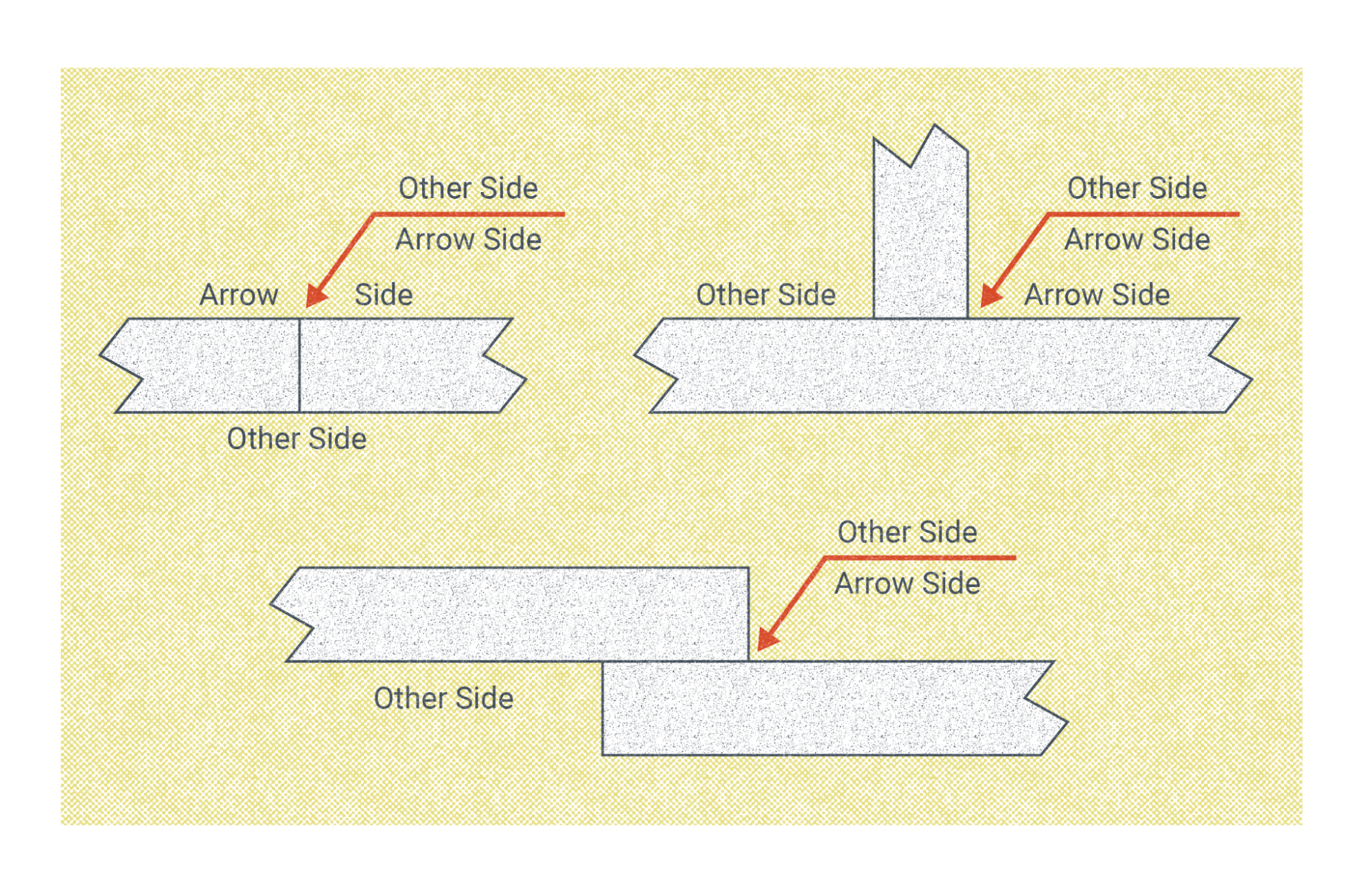
Whether the information is displayed on the top or bottom of the reference line also has special significance. Most weld joints have two sides to them, and the location of information on the reference line accounts for this. Information below the reference line refers to the side of the joint the arrow is directly pointing to while information above the reference line applies to the joint on the opposite of the side the arrow is pointing at (see Figure 16.29).
Tails are opposite the arrow on reference lines. The tail is not always necessary, but when present it serves an important purpose. The tail serves as a catchall for any information that may need to be written out about the weld. For instance, if a specific weld process is required a note reading “GMAW,” “SMAW,” or “FCAW” may appear at the tail. Similarly, if the weld in the symbol is to be applied in multiple places a note reading “3 side” or “3 places” would be written. In some cases a single weld symbol may be used for many weld joints, and the word “typical” (or its abbreviation, TYP) would be written in the tail.
Pictorial Elements
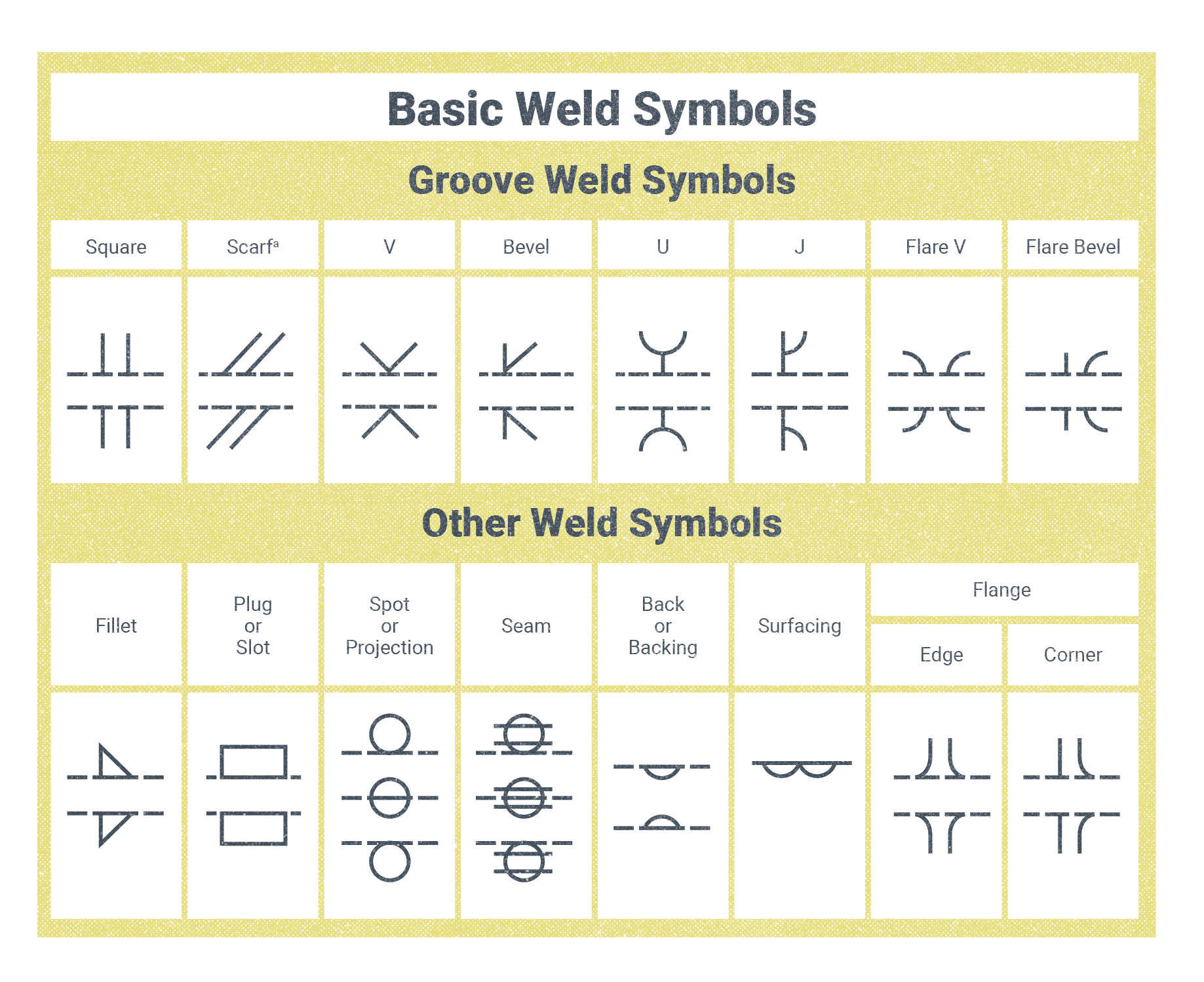
There are a number of symbols, or small pictograms, used in welding symbols. Symbols that appear on the reference line that indicate whether it is a fillet weld or specific type of groove weld are called weld symbols. Don’t confuse this with the term welding symbol which, as covered at the top of this section, refers to the entirety of information conveyed on the reference line and by the arrow and tail. The pictorial weld symbols are drawn so that their shape approximates that of the finished weld or of the groove the weld will be deposited in. This helps to make the weld symbols more intuitive.
Groove Weld Symbols
In all the groove weld symbols, two parallel dotted lines run horizontally. From there comes a lot of variety.
Square: Two parallel lines are squared off of the top dotted line, running vertically. The same arrangement of lines squares off of the bottom dotted line. The symbol looks a like a four-way road intersection.
Scarf: Two parallel lines run diagonally off of the top line and off of the bottom line.
V: A V shape rises off of the top line, and the same shape runs down from the lower line.
Bevel: One straight line and one diagonal line are connected to each other at the center of the top horizontal line (forming a V with a straight edge and an angled edge). The bottom line has the same marking, but with the V shape angled down.
U: A straight line runs perpendicular to the center of the top line, and a curved U shape sits on top of it. The same shape is repeated on the lower horizontal line but with the U shape extending below it.
J: A straight line runs perpendicular to the top and to the bottom lines. About two-thirds of the way up the perpendicular lines, a curved line extends out to the right. The same shape is mirrored on the bottom line.
Flare V: About one-third of the way from the left of the top horizontal line, a short, arched line curves to the left and about one-third of the way from the right of the top horizontal line, a short, arched line curves to the right. The same lines are repeated in the same distances, except upside down, on the lower horizontal line.
Flare Bevel: About one-third of the way from the left of the top horizontal line is a perpendicular straight line and about one-third of the way from the right edge of the line an arched line curves to the right. These lines are repeated, pointed down, on the bottom horizontal line.
Other Weld Symbols
Fillet: Two parallel dotted lines run horizontally. On the top horizontal line, in roughly the center, a right triangle is depicted. The horizontal line forms the bottom edge of the triangle, while the hypotenuse is pointed to the right. The same marking appears on the second horizontal line, except the triangle is upside down.
Plug or Slot: Two parallel dotted lines run horizontally. A rectangle is centered on all but the very edges of the top line. The same drawing is repeated on the lower horizontal line, except the rectangle faces downward instead of up.
Spot or Projection: Three parallel dotted and horizontal lines are pictured. On the top-most horizontal line, a perfect circle sits in the center, just slightly connecting with the line. On the middle horizontal line a circle is bisected by the line. And in the bottom horizontal line, the circle appears centered and touches but hangs below the line.
Seam: Three parallel and dotted lines run horizontally. A perfect circle is centered sitting on top of the top-most horizontal line, and the circle is bisected at the top and bottom edges by short, solid horizontal lines. On the second dotted line another circle, bisected at the top and bottom edges by short, solid horizontal lines, appears but is bisected by the line. In the bottom horizontal line, the circle appears below the line, but it is still touching it. The third circle is also bisected at the top and bottom by two short, solid horizontal lines.
Back or Backing: Two parallel dotted lines run horizontally. On the top line, an edge of a circle points downward. On the bottom line an edge of a circle points upwards.
Surfacing: A single solid line runs horizontally. Two half circles are attached to the line, both pointing down. The half circles touch in the center of the line.
Flange Edge: Two parallel dotted lines run horizontally. About one-quarter of the way from the left edge of the top line a small J-shaped line appears . About one-quarter of the way from the right edge of the top line, a backwards J-shaped line appears. The same lines are repeated, upside down, on the lower horizontal line.
Flange Corner: The corner flange line is similar to the flange edge; however, rather than a J-shaped line the left line is straight and perpendicular to the horizontal dotted line while the right line is a backwards J-shaped line. The bottom line appears as a mirror-image reflection of the top line.
Contour Symbols
Contour symbols are small symbols which appear directly above or below the weld symbol, They indicate the desired contour of the weld face. Either a convex, concave, or flush contour symbol may be used. How strictly the contour of the weld must be shaped can be subject to welding code requirements. And if a contour symbol does not appear, then it should be assumed the weld is acceptable regardless of how the weld face is contoured.
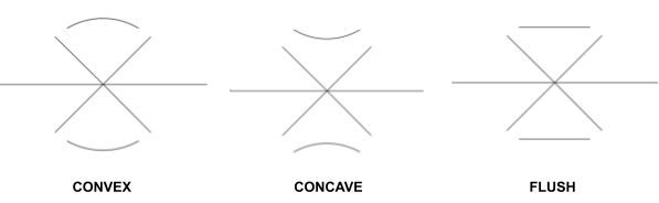
In cases when a contour symbol is used, a finish designator may also be shown. Finish designators are letters that appear above or below the contour symbol to designate what method should be used to shape the final weld:
- C indicates chipping.
- G indicates grinding.
- M indicates machining.
- R indicates rolling.
- P indicates planishing.
- U indicates unspecified (any method may be used).
Grinding and machining are the most commonly indicated methods for achieving a given contour. If no finish designator is shown, any method may also be used, or the weld may be acceptable without further finishing if the contour is correct.
Field Weld and Weld All Around Symbols
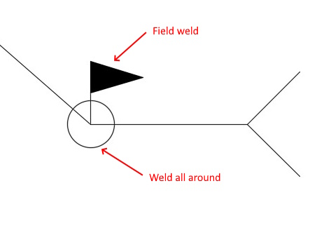
There are two more pictorial elements to welding symbols to cover. They are the field weld and weld all around symbols. Both these symbols are located at the junction of the arrow and reference line.
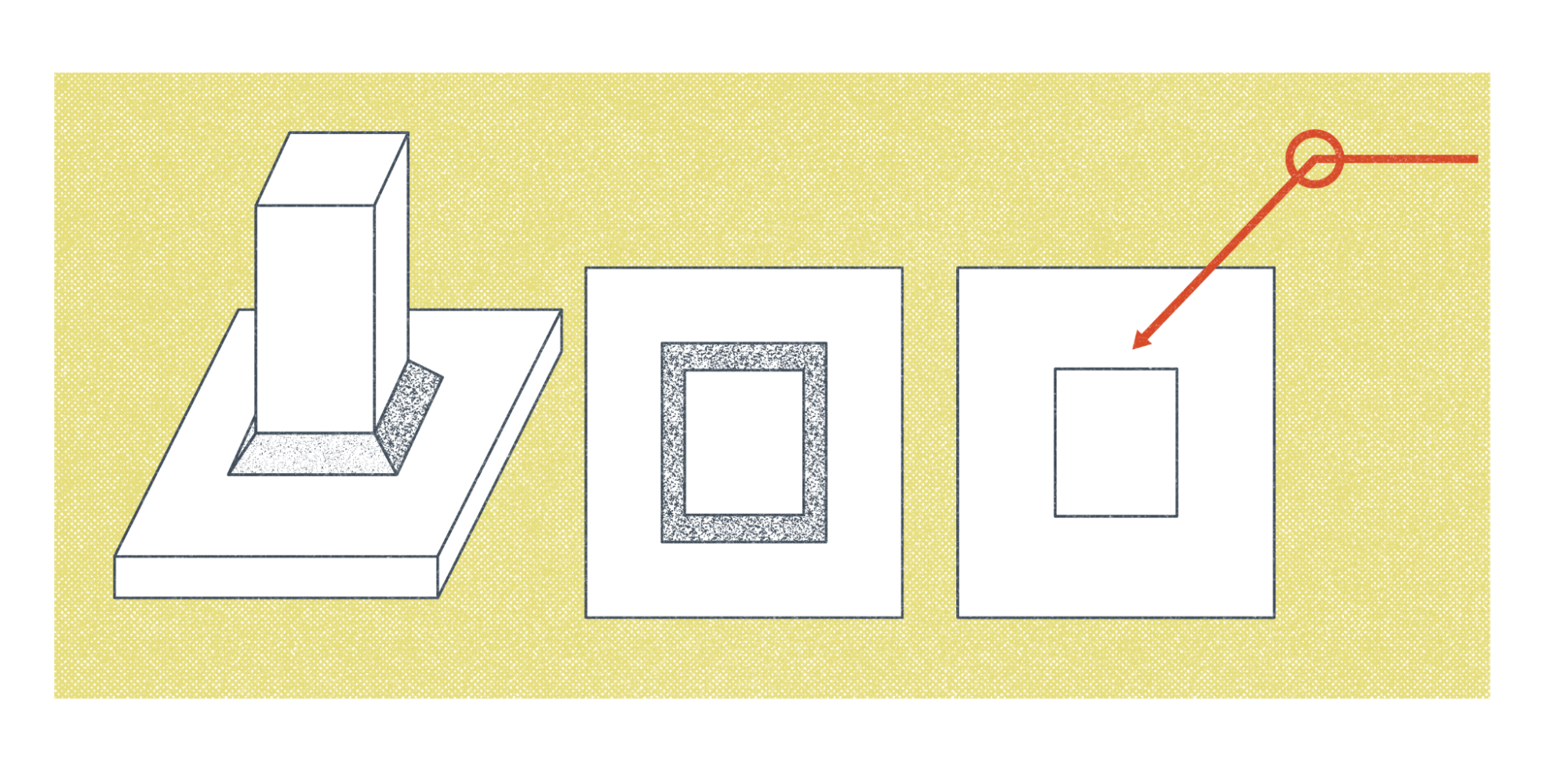
The weld all around symbol looks like a circle centered on the junction of the arrow and reference lines. If this symbol is present, it communicates that the weld should extend all around the joint. It is useful when welding shapes with more than two distinct sides, such as an I-beam, pipe, or square tubing.
A field weld symbol is used to indicate welding should take place in the field rather than in the shop. Many welding projects involve prefabricating part of a project in a controlled shop environment, with further assembly and welding required at the job site. It looks like a flag on a pole or a solid triangle attached to the weld by a short straight line.
Attributions
- Figure 16.27: The Parts of a Welding Symbol © American Welding Society, illustration by Nicholas Malara (SBCTC Illustrator) Used with permission from the rights holder, the American Welding Society.
- Figure 16.28: Arrow, Reference Line, Tail by Cameron Kjeldgaard, for WA Open ProfTech, © SBCTC, CC BY 4.0
- Figure 16.29: Significance Of The “Arrow Side – Other Side” Parts Of The Welding Symbol Reference Line by Nicholas Malara, for WA Open ProfTech, © SBCTC, CC BY 4.0
- Figure 16.30: Basic Weld Symbols by Nicholas Malara, for WA Open ProfTech, © SBCTC, CC BY 4.0
- Figure 16.31: Contour Symbols by Cameron Kjeldgaard, for WA Open ProfTech, © SBCTC, CC BY 4.0
- Figure 16.32: Field Weld and Weld All Around Symbols by Cameron Kjeldgaard, for WA Open ProfTech, © SBCTC, CC BY 4.0
- Figure 16.33: The Significance Of The “Weld All Around” Weld Symbol by Nicholas Malara, for WA Open ProfTech, © SBCTC, CC BY 4.0
The entirety of information conveyed on the reference line and by the arrow and tail. Different from weld symbols, which are pictorial symbols that approximate the finished weld.
