8.4 SMAW Operation and Welding Techniques
David Ridge
Welding Basics
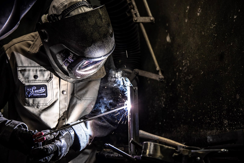
Now that you have all of the preliminary background information, you are ready to strike your first arc. (Be sure to read Chapters 2, 3, and 4 welding safety and PPE and ensure that you are familiar with and possess all the necessary PPE and tools required. If not, take this opportunity to do so.)
This section describes the techniques you will use when welding with the SMAW process. You will learn the basics of striking an arc, breaking an arc, and the acronym CLAMS, which stands for current, arc length, angle, manipulation, and travel speed. This acronym helps us remember the elements of good welding technique and can be applied to every welding process.
Getting Comfortable
The first step in making any weld is actually to get into a comfortable position. Being comfortable and having freedom of movement to perform the weld is imperative to making good welds, especially as a beginner. This can take whatever form makes sense to you, as everyone is different. However, consider the following points as general guidelines for good welding posture:
- Whether you are sitting or standing, try to keep your torso as upright as possible. Try to find something to brace your body or a leg against.
- If the object you are welding can be moved freely, try to position it at a height somewhere between your chest and your waist. This allows you to both see and reach the weld zone easily. If the object cannot be moved, instead try to position yourself so that the weld you are making is as close to the area between your chest and your waist as possible. Welding below your waist or above your shoulders will tire you out quickly and it is hard to see the weld.
- Hold the stinger (electrode holder) in your dominant hand, and then brace that hand with your off-hand. For example, if you are right-handed, you will hold the stinger in your right hand and then brace that hand with your left.
- Find something to rest the elbow or forearm of your bracing hand on. This can be almost anything: the workbench you’re using, a wall if you are next to one, or even a clamp attached to the piece you’re welding. It is important to understand that you don’t need to lean all of your weight on that arm—instead, it is there to steady you. As you will find out when welding, everything but the arc becomes dark through your hood. Because of this, your brain automatically thinks you are losing your balance and will cause you to sway. Having your arm in contact with a solid object will reduce this effect.
- Most of the movement during welding should come from your wrists and forearms. Avoid needing to move your elbows and shoulders and try to keep your elbows as low and close to your body as possible.
- Before actually welding, make a few test runs along the joint to be welded to ensure that nothing will impede your movement when you make the actual weld. Notice whether your bracing hand can easily slide along the joint without getting caught and if you can reach the entire length of the weld easily. Test runs can also help you to know if are in a good position to see the weld at all times.
Being comfortable during welding increases your stability and range of motion, reduces your rate of fatigue, ensures good visibility, and, overall, allows you to weld better for longer.
Striking an Arc
Once you have your welding machine and workstation set up and gotten into position, you will need to strike an arc to start welding. This sounds simple enough but requires practice to do effectively.
In order to initiate the arc with SMAW, you must touch the tip of the electrode to the base metal, then raise it slightly above the base metal surface. This is actually quite challenging because when you touch the live electrode to the grounded base metal, it creates a short circuit in the flow of electricity, which often causes the electrode to stick to the base metal.
There are two basic techniques that can be used to prevent the electrode from sticking. In the first, you lightly scratch the tip of the electrode across the surface of the base metal for a short distance, much like striking a match. This motion should be done quickly and lightly—the more pressure you apply, the more likely it will be that the electrode will stick.
In the second technique, you hold the electrode slightly above the base metal surface, then move it straight down and tap the surface lightly before raising it slightly again. You can think of this motion like how you would strike a pool ball with a cue stick. In fact, many beginner welders start with this method by holding on to the end of the rod with their off-hand, much like a pool cue. Once the arc is started, they move their hands back to brace their dominant hands.
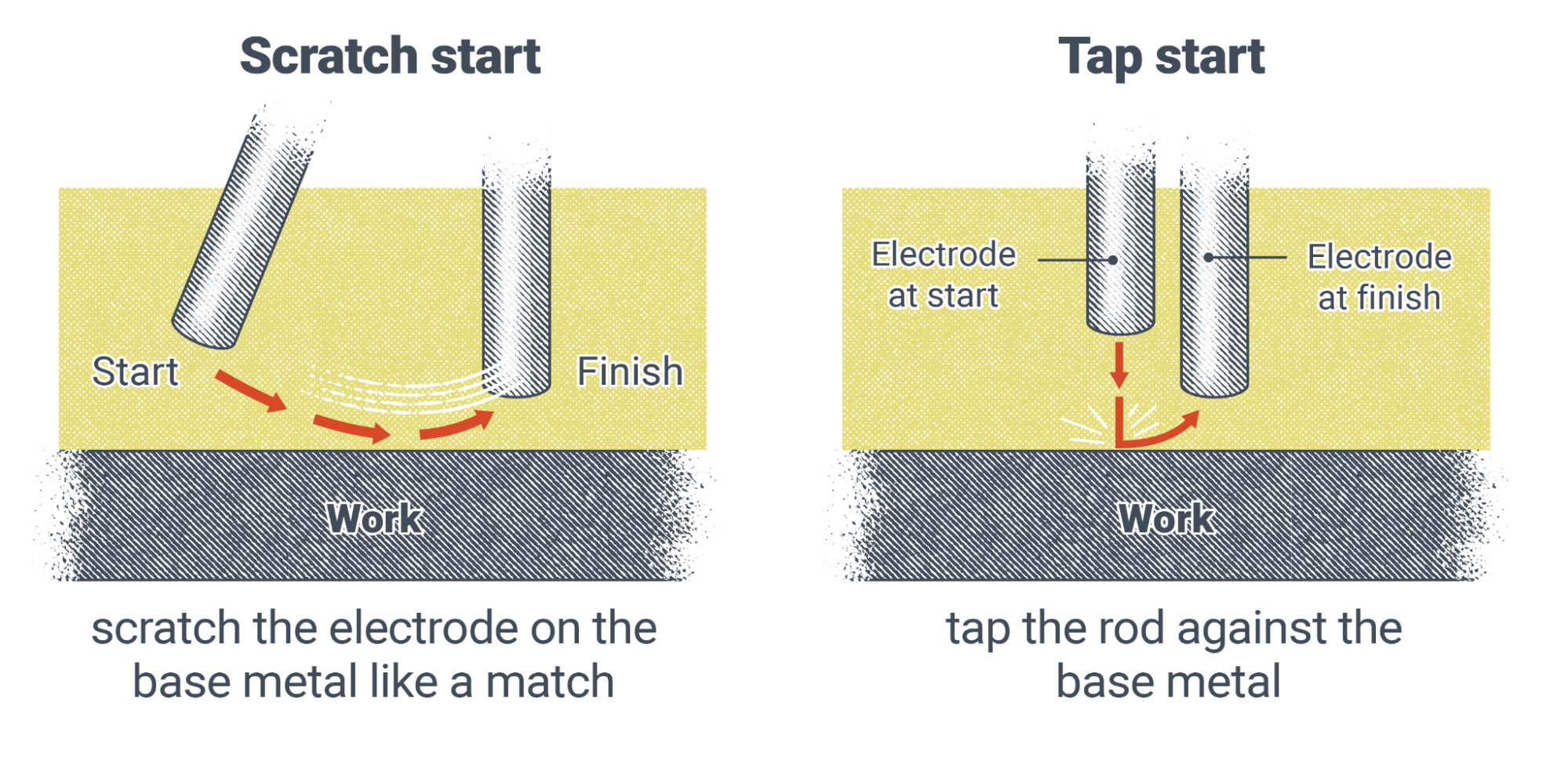
While these techniques will help with starting the arc, they are not guaranteed to keep the rod from sticking every time. Sticking happens at some point to every welder who uses SMAW, no matter their experience level. Try not to get frustrated if it is difficult to strike an arc right away. With practice, you will become proficient.
Breaking the Arc
We should also cover how to break or stop the arc. When you come to the end of a weld, you might be tempted to slowly pull the electrode away from the base metal—but you should resist, as this is an incorrect method.
Instead, as you come upon your stopping point, hold the arc at the end of the weld for a second or two. This helps fill in the weld crater. Then quickly snap the electrode away from the base metal, either in the direction you were traveling or back over the weld. This will efficiently break the arc and prevent any unwanted arc strikes outside the weld zone.
C is for Current
Now we’ll progress into the elements of the CLAMS acronym. The first letter, C, stands for current. The moment you turn your welding machine on, you must decide on the type and amount of welding current needed. SMAW uses constant current (CC) welding power. If your welder is a multi-process machine and isn’t automatically set to CC, then you will need to change the type of welding power. Iinstead of CC you may see a selection labeled “Stick” or “SMAW”—those will set the machine to CC power.
Next, you will need to determine your polarity. Looking at the classification for the electrode you are using, you can determine whether the machine should be set to DCEP, DCEN, or AC. Select the correct polarity by adjusting the switch, knob, or button on the welder or by changing which port the electrode and work leads are plugged into (refer to SMAW Setup in Section 8.2).
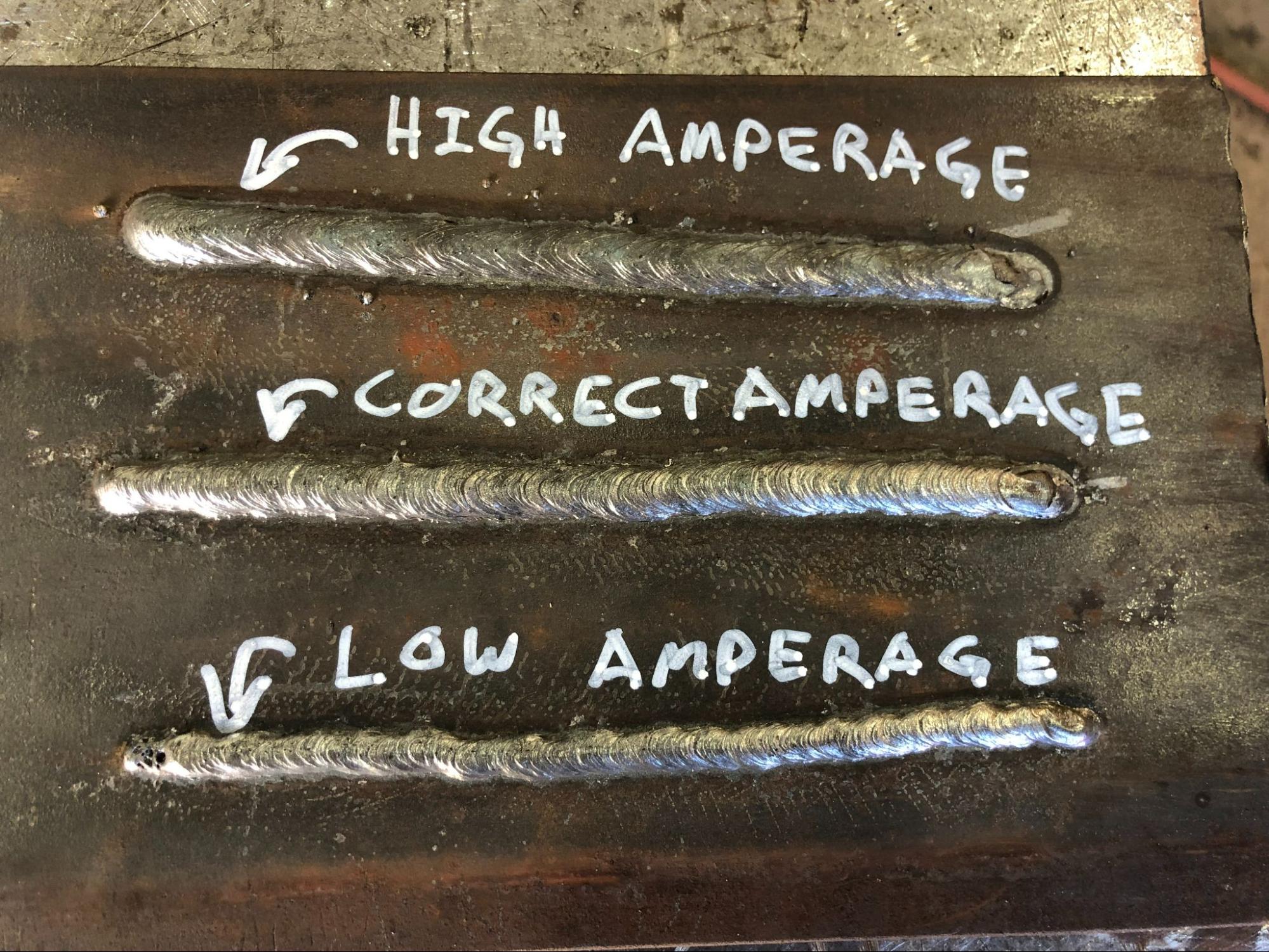
Once you have the correct power type and polarity you can set your amperage. The most important current setting for SMAW, amperage has the greatest effect on the quality of weld penetration and weld bead shape. It is very important to select the correct amperage for the electrode you are using and the base metal to be welded. As an example, a one-eighth inch diameter E7018 has a recommended amperage range of 90–160 amps (the recommended amperage for each electrode can be found in its product information from the manufacturer). However, this must be balanced against the base metal thickness. So if you were to weld on a piece of one-quarter inch thick steel plate, you would find that the appropriate amperage would actually be around 110–125 amps. Thicker plate would take more amperage, and thinner plate would take less.
The process of troubleshooting the correct amperage range takes some time and experience, especially since there are a number of other factors that influence it, which can include welding position, weld joint configuration, the length of your leads, and preheat, among other things. Even the machine you are working with can be a factor, as each different welding machine may run slightly differently.
When on the job, your supervisor can instruct you on an amperage range as a good starting point, but you will likely still have to fine-tune your settings from there. The best way to know how to troubleshoot your amperage setting is to practice doing it as much as possible. Look for some of the following issues when welding, which can indicate incorrect amperage:
- If the finished weld bead is narrow with a high crown and little penetration, your amperage may be too low.
- If the finished weld bead is wide and flat with excessive penetration and a lot of spatter, your amperage may be too high.
- If the arc is difficult to start and the electrode sticks to the base metal constantly when striking the arc, or if it seems like the arc is almost sputtering out during welding, your amperage may be too low.
- If, while welding, the arc digs into the base metal at the edges of the weld or even burns through the base metal, your amperage may be too high.
- If you notice that the weld pool is excessively long and shaped like a teardrop rather than an oval, your amperage may be too high.
Another control that may be adjusted is the arc-dig or arc-force setting. This setting is not essential for making a good weld, but can help make welding easier. If your machine has this control, you can adjust the “crispness” of the arc, meaning it will be narrower and seem to drive more into the base metal. A higher arc-dig setting will make the arc more crisp, though it does not measurably improve penetration. This is useful for welding in a tight corner or groove or for welding an open root (discussed in Chapter 15: Weld Identification). This setting also helps keep the electrode from sticking to the base metal when holding a short arc length. Turning the arc-dig down will create a “softer” arc, meaning it will be wider and less forceful. This helps if you are trying to spread out the weld pool more when welding on a flat surface or on thinner material.
Before moving on, a note about safety with regards to current settings is that none of the settings or controls mentioned should be adjusted during welding. When working with certain older welding machines it is even recommended that the machine be powered off before adjusting settings like polarity. Doing so prevent damage to the machine, but also ultimately protects you since a damaged machine can cause you harm.
L is for Arc Length
The second letter of the CLAMS acronym stands for length, referring to arc length: the distance that the arc travels through the air. It is measured from the tip of the electrode to the surface of the weld pool. Arc length is an important welding variable with any welding process, and particularly with processes that use CC welding power.
In the section about setting the current for welding, you may have noticed that there was no mention of a control for voltage. Both amperage and voltage are a part of every electrical current, so where is the voltage control for SMAW? In a sense, arc length is the voltage control, and it’s manually adjusted by your motions throughout the weld (remember that voltage is electrical pressure or force). The distance that the arc must travel through the open atmosphere determines the voltage applied to the weld. As the arc length increases, the voltage increases, and vice versa. This is because it requires more voltage for the arc to travel across a greater distance.
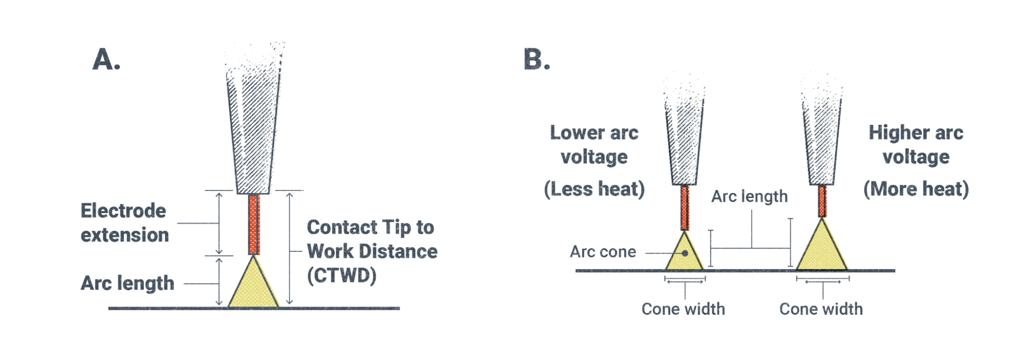
Because SMAW uses CC power, the overall electrical power in watts always remains the same. This means that changes in voltage due to changes in arc length will also change the amperage being applied to the weld. If the voltage increases, the amperage will decrease, and vice versa.
To consider an example, let’s say you set the amperage on the machine to 80 amps and then maintain an arc length that requires 24 volts. Using the formula from Chapter 5, we know that 24V × 80A = 1,920W. At that amperage setting, the welding machine will always try to maintain that 1,920W output. If the voltage were to increase to 30V because you increased the arc length, the amperage would automatically decrease to 64A because 30V × 64A = 1,920W. Conversely, let’s say the voltage decreased to 20V because you held a tighter arc length. We know that the amperage will increase to 96A because 20V × 96A = 1,920W. It is important to note that although this is the theory of how CC welding power works, in in reality these numbers will not be perfect. This is simply because no welding machine or welding conditions is perfect. However, these formulas provide a close approximation of what actually takes place.
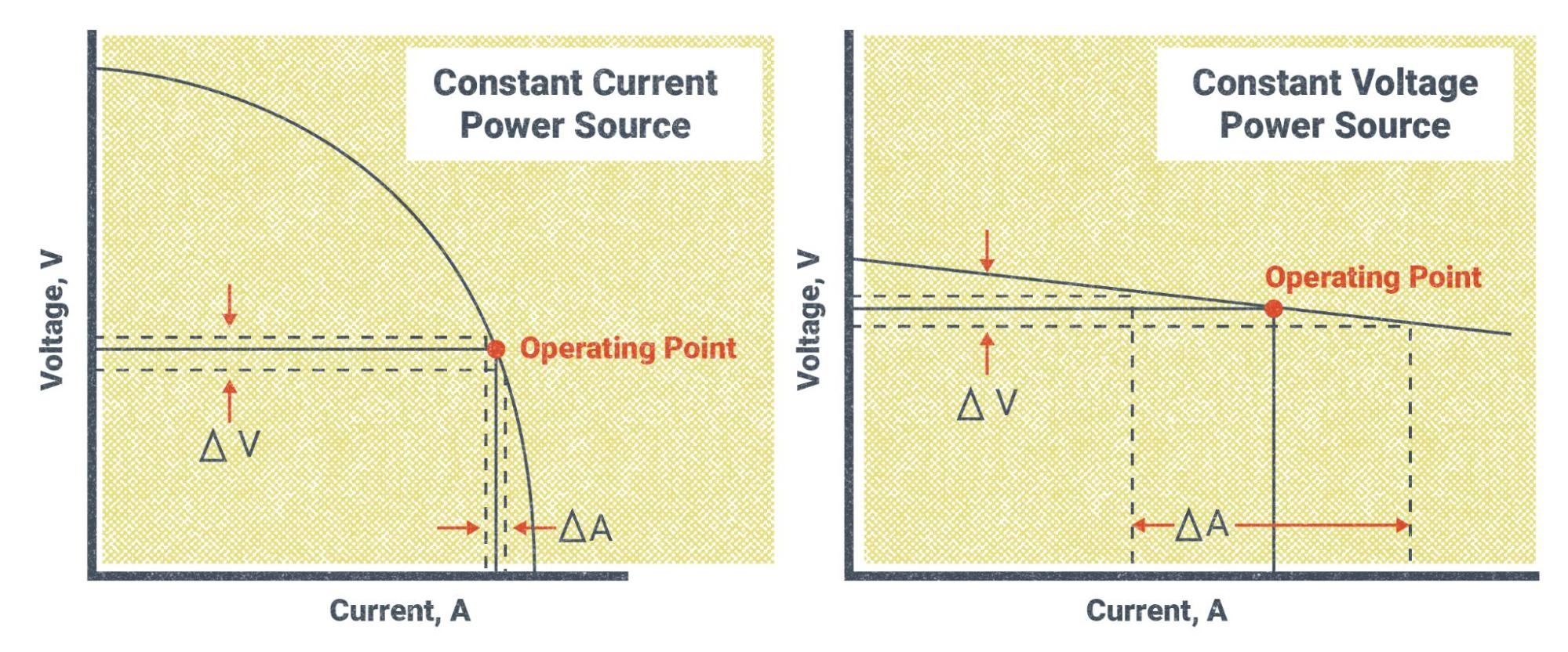
Voltage determines the fluidity of the weld pool. More voltage means the molten metal is more fluid, and less voltage has the opposite effect. What you need to take away from this is that voltage affects how easily the weld pool spreads out across the base metal.
Welders must maintain a balance with the arc length. If the arc length is too long, the arc becomes violent and the weld pool becomes too hot and fluid. This usually results in defects like excessive spatter and undercut, as well as poor weld quality in general. Increasing the arc length will, at a certain point, not create a weld pool but will simply deposit globs of molten metal on the surface of the base metal. On the other hand, if the arc length is too short, the weld will not spread out and will pile up on itself, which leads to defects like overlap (also called cold roll) and lack-of-fusion (LOF) because the arc is not hot enough to melt the filler and base metals completely. Further shortening the arc length will result in the end of the electrode sticking in the weld pool.
In general, the correct arc length for most electrodes is said to be equal the electrode’s diameter. This means if you were welding with an E7018 electrode with a diameter that is one-eighth of an inch, you would try to maintain a one-eighth inch arc length. Doing so is easier said than done. You must remember that the electrode is melting off and getting shorter as you progress along the weld. One of the most difficult skills for a new welder to master is the ability to lower the electrode towards the weld pool at a consistent rate. However, with time and practice, you will become proficient.
Arc Blow
Before moving on to cover the next letter in the CLAMS acronym, we should discuss a problem that can occur during welding. Known as arc blow, it causes the arc to wander haphazardly with little ability for the welder to control it. It can cause weld defects such as undercut, LOF, and slag inclusions.
It’s a phenomenon that occurs due to the magnetic field created by the flow of electricity through the base metal. Arc blow is hard to predict or control because it is related to the shape and joint configuration of the weldment and the amount of welding power flowing through it. Some methods for trying to control arc blow include:
- Move your work clamp so that you are welding away from it
- Use multiple work clamps attached at different points on the weldment
- Use AC, if possible
- Weld at the lowest amperage possible
- Keep as tight of an arc length as possible
- Try adjusting the arc-dig to be more crisp
Though these tips can help, sometimes it is impossible to eliminate arc blow completely. Experimenting with different strategies will help you decide how to best handle an instance of arc blow.
A is for Angle
The next letter in the CLAMS acronym is A, standing for angle. You may hear this referred to as rod angle or electrode angle (or gun angle for MIG welding and torch angle for TIG welding). Rod angle actually refers to two different angles: travel angle and work angle.
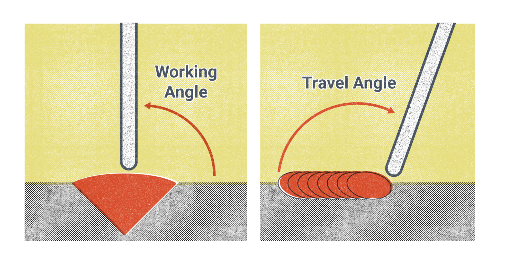
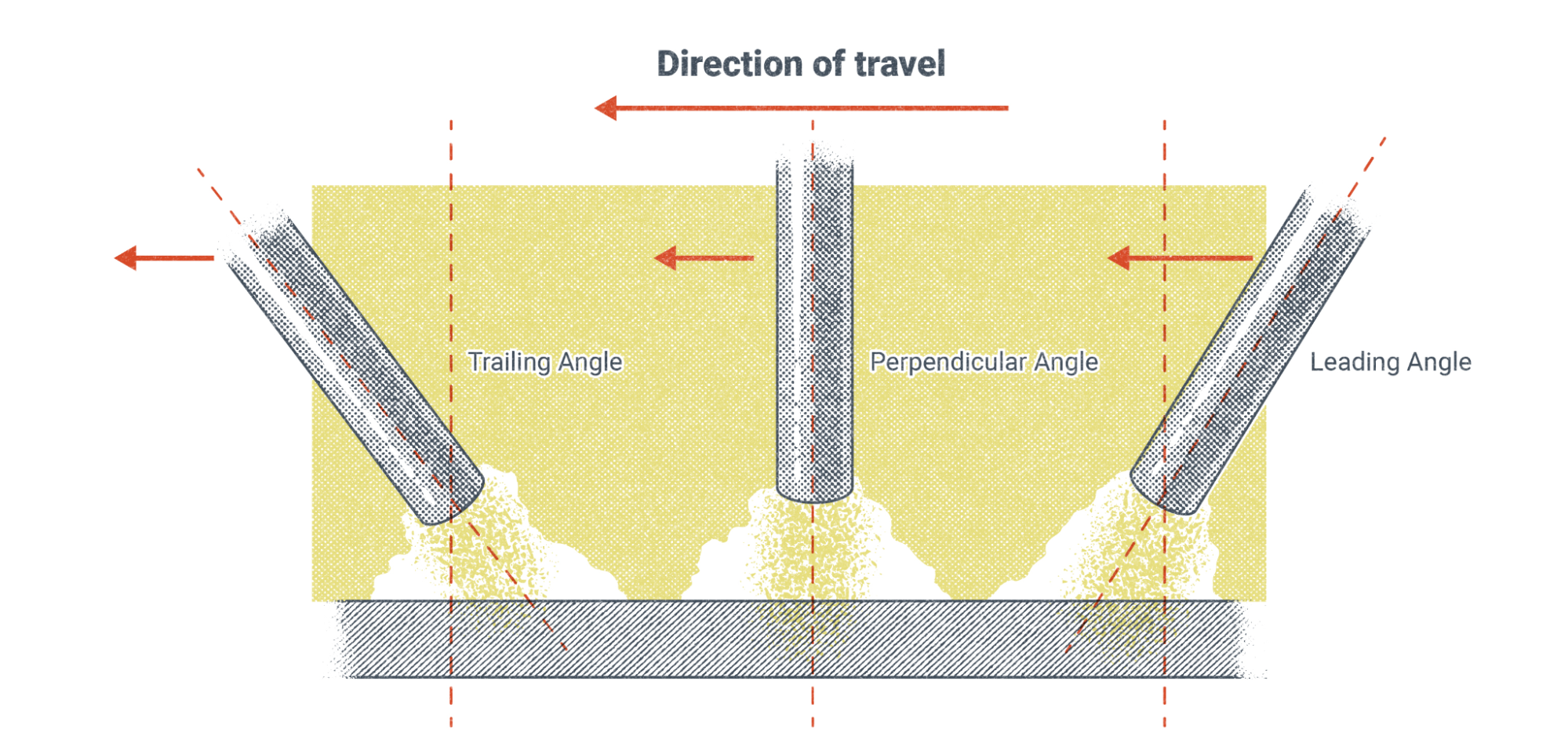
Travel angle is the angle of the welding rod in relation to the direction the weld is progressing. There are generally considered to be three different travel angles.
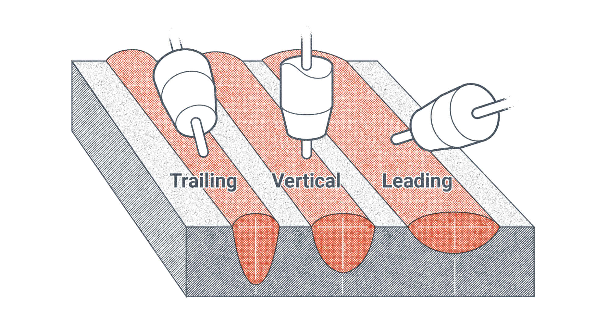
A trailing angle is when the tip of the electrode is angled away from the direction the weld is traveling while the end held by the electrode holder is angled toward the direction of travel. This puts the weld pool slightly behind the tip of the electrode, and you may hear it said that you are “dragging” the weld. This is the most common travel angle used for SMAW.
A leading angle is formed when the tip of the electrode points toward the direction of travel and the end of the electrode in the stinger trails behind. This puts the weld pool slightly ahead of the tip of the electrode, and you may hear it said that you are “pushing” the weld. A leading angle is often less desirable with SMAW because of the tendency for slag to be deposited ahead of the weld and then trapped underneath or within the weld as the weld pool passes over it. These slag inclusions are a major defect in a completed weld and might cause it to fail under extreme stresses. While the risk of this defect is a major concern, some experienced welders may make effective use of the leading angle.
A perpendicular angle is a travel angle that puts the electrode straight up and down over the weld pool at 90-degrees to the plane of the weld.
There are different reasons to use any of these travel angles. Welding position has a lot to do with it, as well as weld joint configuration. For example, you are more likely to use a leading angle when welding in the vertical up position, but you may prefer a trailing angle for flat or overhead welds. Sometimes the placement of a weld is in such a constricted space that it is only possible to use one angle. Other times, the placement will force you to change angles partway through the weld.
Another reason you may choose one angle over another is the thickness of the base metal compared to the desired weld penetration. It is generally accepted that a trailing angle produces a weld with deep penetration and a tall, narrow weld face whereas a leading angle produces a wide, flat weld with less penetration. A perpendicular angle is somewhere in between.
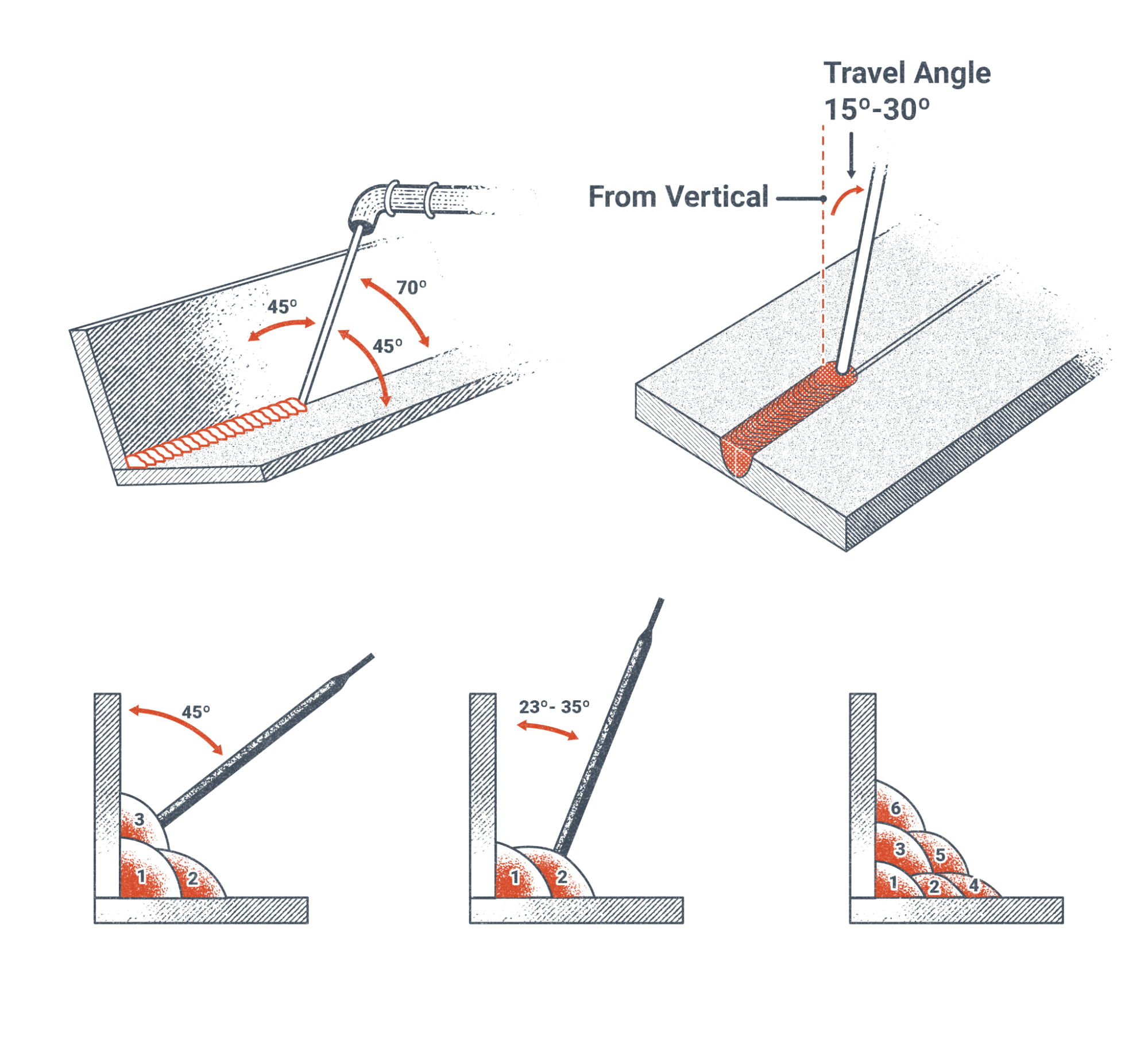
Whichever angle you use, it is important to note that extreme angles are undesirable. This means that whether you are using a trailing or leading angle, you should attempt to keep the electrode between 15-degrees to 30-degrees from perpendicular.
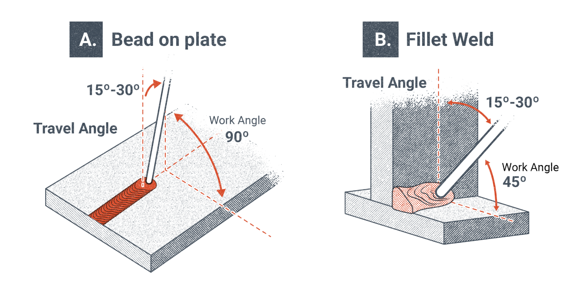
Next is the second type of rod angle, which is work angle. It is the angle of the electrode in relation to the base metal. Work angle is somewhat subjective, but the basic idea is that the work angle is used to force weld metal more to one side of the weld than the other. This is not always necessary, so a perpendicular work angle is used to deposit weld evenly.
Perhaps the best example of work angle is on a multi-pass weld, such as in a T-joint or weld groove. Each successive weld pass requires you to adjust the work angle slightly to force the weld one way or the other. Unfortunately, there are no solid rules about work angle, and it is something that every welder learns to account for through experience.
The angle of your welding rod is an important factor when making any weld. New welders often have trouble maintaining a consistent rod angle while welding because the act of moving the rod and their hands together along the weld joint while continually lowering the rod as it shortens is unfamiliar. Practice finding a comfortable position and being able to freely move your hands along with the electrode holder and rod and, in time, you will find it easy to keep a proper rod angle.
M is for Manipulation
The next letter in the CLAMS acronym is M, which stands for manipulation, though some might say it stands for motion. Either way, the focus is on what movement you’re making with the welding rod. It’s important to note that this is not the movement of maintaining your arc length, your rod angle, or your progress along the weld joint. Rather, what we are talking about here is what’s referred to as the weave pattern or oscillation. The main purpose of manipulating the electrode in this way is to make the weld bead wider. There are a number of different weave patterns or oscillations that can be used. Each one has a purpose and, depending on the situation, some are better or worse.
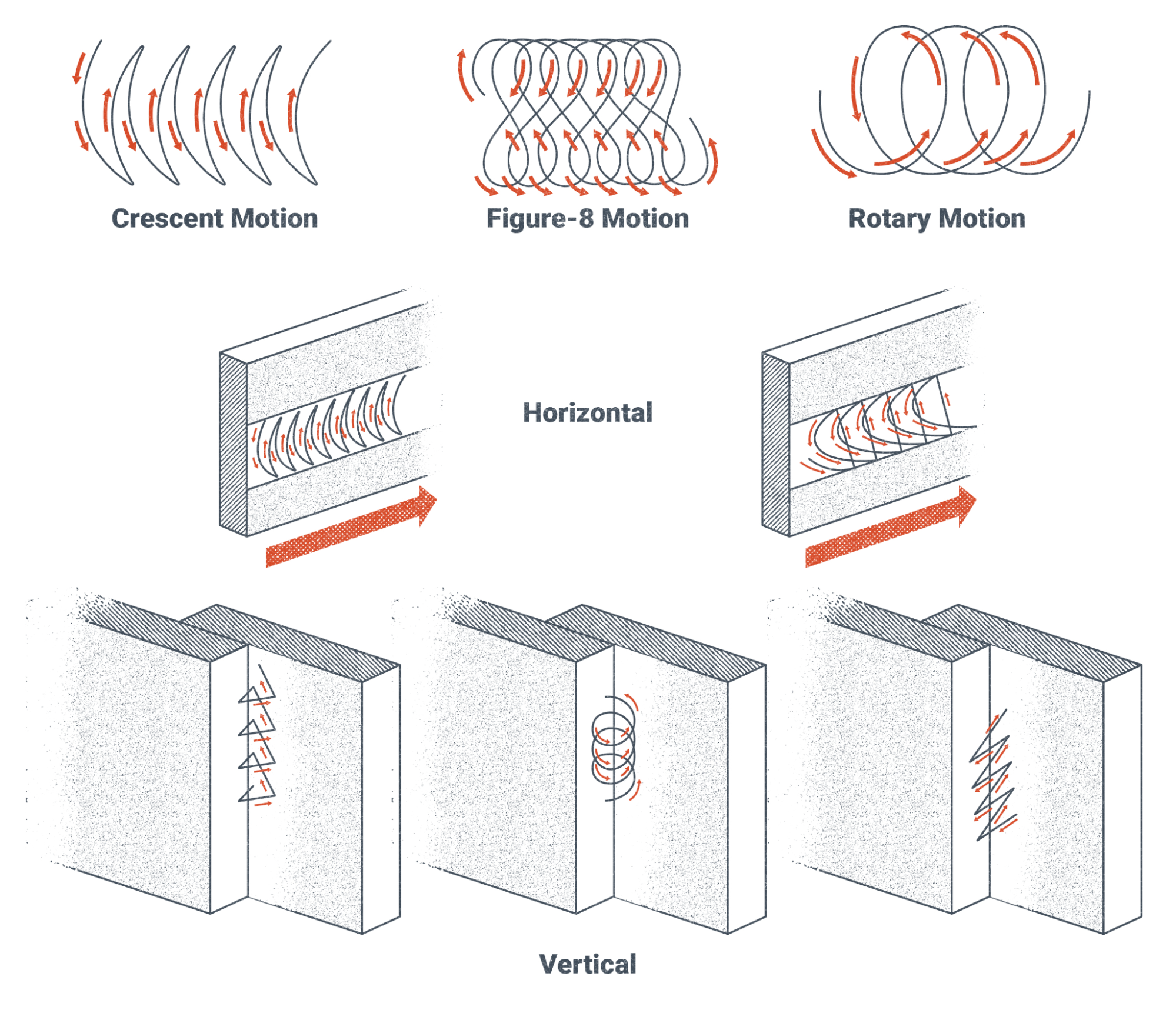
The patterns shown in Figure 8.35 are just a few of the weave patterns that have been developed. Simply by modifying a pattern that you are familiar with, you could create a new pattern. There is no hard rule that tells you which weave pattern or oscillation you should use at any given time or instructs that you need to use any such movement. It is often quite acceptable to make stringer beads, which are straight weld beads made without side to side motion. Usually it is up to the welder to decide which manipulation they want to use. You will learn through trial and error which ones work for specific situations, although it is helpful to ask more experienced welders for tips in this area.
S is for Speed
The last letter in the CLAMS acronym is S, standing for speed. Speed is the most determinative factor influencing how big the weld bead turns out. There are two speeds to be aware of: travel speed and manipulation speed. Travel speed is how fast you are progressing along the weld joint and manipulation speed is how fast you are weaving or oscillating. Accordingly, manipulation speed is not a factor when making stringer beads.
f you are working off of a welding blueprint, there will almost always be a callout for the weld size on every weld (blueprints and welding symbols are covered in Chapter 16). Adjusting your speed is the best way to control the size of a weld: A slower speed will make the weld bigger, and a faster speed will make it smaller. This is true whether you are making a single-pass weld or multi-pass weld. For SMAW, a general rule for weld size is that you want the weld pool to be approximately twice the diameter of the electrode you are using. For example, if you are using an electrode whose diameter is one-eighth of an inch, you would want to keep the weld pool at about one-quarter of an inch wide.
Weld defects can result if your speed is incorrect for the amperage and size of rod you are using. A speed that is too fast will often cause undercut at the edges of the weld. Too slow of a speed will likely cause overlap. Paying close attention to the weld pool as you are welding will help you determine how fast or slow you should be moving.
The Importance of the Weld Pool
Now that we have finished defining the CLAMS acronym, I think you will agree that there is a lot to pay attention to during welding. Being able to focus on each factor simultaneously is one of the biggest challenges for new welders. It’s best to start small and try and focus on one thing at a time until you get the hang of it. For example, spend a whole training day just striking an arc, another day focusing on your arc length, and another practicing your angle or travel speed, etc. Learning to weld takes a considerable amount of patience, but if you are diligent and stick with it you will be surprised how quickly you will improve.
In addition to the CLAMS factors, however, there is one more aspect of making a weld you need to pay close attention to, and it is quite possibly the most important: being able to see and read the weld pool at all times. If you cannot see the weld pool, you must adjust or change whatever it is that is keeping you from seeing it. The importance of this cannot be stressed enough.
Learning this skill is, by far, the most difficult thing for a new welder to do. Inexperienced welders tend to use the arc or their rod as the focal point of their vision. As you develop your welding skills, you must train yourself to focus primarily on the weld pool and monitor everything else through your peripheral vision. Good welders know that the weld pool tells them everything they need to know about how the weld is going. This is true of any welding process.
With SMAW, the weld pool should be roughly oval or egg-shaped. Look out for these issues:
- If the weld pool is elongated or has turbulence on the surface, that can mean that you are running too hot and need to turn down your amperage.
- A narrow weld pool can indicate an amperage that is too low or a travel speed that is too fast.
- An overly wide weld pool can mean a travel speed that is too slow.
- A weld pool that is off to one side of the electrode can indicate a bad work angle.
Practice keeping the weld pool as your focal point and learning to interpret its indicators. Ask questions of instructors and other welders if you don’t understand something about it. Once you can effectively interpret what the weld pool is telling you, you are well on your way to being a better welder.
Special Safety Considerations
Before we conclude this chapter, it would be a good idea to go over some safety considerations that are commonly associated with SMAW. These are in addition to general safety considerations for welding, such as hazards like smoke, sparks, hot metal, sharp edges, and electricity. Refer to Chapters 2, 3, and 4.
With SMAW, there are some specific hazards that you should keep in mind. Remember that when the welding machine is on, the electrode holder is always live. Damaged electrode holders can have exposed contact surfaces that could accidentally strike an arc if touched to the base metal. This also means that any time an electrode is held in the holder, the electrode is live. Never set the electrode holder down with an electrode still loaded in it. Be aware of any broken flux on the electrodes. Any place where the flux is broken off exposes the metal rod underneath and presents the potential for an accidental arc strike. Aside from being dangerous, unintentional arc strikes on the base metal are undesirable, as in many welding situations arc strikes outside the weld zone are considered a defect and may cause the piece to be scrapped.
Another common occurrence with SMAW is related to arc strikes—the end of the electrode may get stuck when you attempt to initiate the arc. New welders are often surprised by it the first time it happens to them. Be aware that if the rod sticks, the electricity continues to flow through the circuit even though there is no visible arc. This can be hazardous for two reasons. First, the machine is operating at the working amperage and voltage. You would not want to touch any of the contact points and become part of the circuit. And second, if the electrode is not immediately broken off the surface of the base metal, it will begin to heat up. After a few seconds, you will see the electrode glow bright orange. That means the rod is in excess of 1,500 degrees Fahrenheit. You would not want to touch the rod at that temperature, even with a gloved hand. If you find that you cannot easily break the electrode off the base metal when it sticks, the next best thing to do is to let go of the rod with the electrode holder. Wait about 10 seconds and then you should be able to easily snap the electrode off of the base metal.
There are a few final things to be careful of. If you are in a situation where you are welding full-time or at least several hours consecutively, beware of fatigue. Welding is a physically and mentally demanding job, and fatigue can set in without you noticing. People are the most careless and at risk for an accident when they are tired. Take breaks at appropriate times, keep yourself hydrated, and be aware of whether you are feeling symptoms of heat stress or heat stroke. Always try to find a way to be as comfortable as you can, whether this means feeling as cool as possible or in a position that does not cause strain, as this will help delay the onset of fatigue.
There is one particular practice you want to avoid related to fatigue. The electrode holder and the welding lead are heavy, and over time your arms will start to feel strained. The temptation when this happens is to wrap the lead around your arm or body. While it is fine to loosely drape the lead over a shoulder, you should avoid wrapping the lead around yourself in a coil. A coiled copper conductor with electricity running through it is an electromagnet—and in this case you would be at the center of it. However, high levels of electromagnetic flux have been shown to be dangerous to humans.
As with any industrial environment, there are always hazards present when welding, whether with SMAW or any other process. Many thousands of welders perform their work every day without incident. These welders know that the best safety practices are to be competent, have common sense, and be aware of their environment. If you do the same, you will not need to endure hazards.
Attributions
- Figure 8.25: Shielded Metal Arc Welding by Weldscientist is released under CC BY-SA 4.0
- Figure 8.26: Striking the Arc by Nicholas Malara, for WA Open ProfTech, © SBCTC, CC BY 4.0
- Figure 8.27: Welds at Different Amperages by David Ridge, for WA Open ProfTech, © SBCTC, CC BY 4.0
- Figure 8.28: Arc Length and Voltage by Nicholas Malara, for WA Open ProfTech, © SBCTC, CC BY 4.0
- Figure 8.29: Volt/Amp Curve by Nicholas Malara, for WA Open ProfTech, © SBCTC, CC BY 4.0
- Figure 8.30: Electrode Angle by Nicholas Malara, for WA Open ProfTech, © SBCTC, CC BY 4.0
- Figure 8.31: Travel Angle by Nicholas Malara, for WA Open ProfTech, © SBCTC, CC BY 4.0
- Figure 8.32: Angle and Weld Profile by Nicholas Malara, for WA Open ProfTech, © SBCTC, CC BY 4.0
- Figure 8.33: 15-30 Degree Angle by Nicholas Malara, for WA Open ProfTech, © SBCTC, CC BY 4.0
- Figure 8.34: Work Angle by Nicholas Malara, for WA Open ProfTech, © SBCTC, CC BY 4.0
- Figure 8.35: Weave Patterns by Nicholas Malara, for WA Open ProfTech, © SBCTC, CC BY 4.0
Constant current is a form of welding power in which the amperage is set on the welding machine and the voltage is controlled manually by manipulating the arc length. As voltage increases during welding, amperage will decrease, and vice versa. Constant current is used with manual welding processes like SMAW and GTAW.
A weld bead is the continuous line of deposited weld or melted base metal made by a single pass of the electrode.
Spatter is a weld defect that occurs during welding when small globules of molten metal land outside the weld pool and stick to the base metal surface.
The weld pool or weld puddle is the area of molten metal directly beneath the electrode that has been melted by the arc.
Arc length is the distance the arc must jump through the atmosphere and is measured from the end of the welding electrode to the surface of the weld pool.
Undercut is a weld defect in which the arc gouges out an area of the base metal along the edge of the weld which then does not get filled back in with weld metal. This leaves a small depression at the edge of the weld.
Overlap occurs when the molten weld pool does not fuse into the base material. The weld pool falls on top of the base material and is not solidly connected to it.
Lack of fusion is a weld defect that occurs when filler metal does not properly adhere to the base metal. This causes a weak spot or break in the weld, or possibly a stress point.
Slag inclusions are weld defects that occur when the weld pool passes over bits of preformed slag and doesn’t remelt them. This causes the slag to be trapped between layers of weld metal.
Travel angle refers to the angle of the electrode in relation to the direction the weld pool is being moved along the weld joint.
Work angle refers to the angle of the electrode in relation to the surface of the base metal and is measured transversely to the longitudinal axis of the weld.
A trailing angle is a travel angle in which the electrode tip is angled away from the direction of travel, putting the weld pool behind the electrode.
A leading angle is a travel angle in which the electrode tip is angled toward the direction of travel, putting the weld pool ahead of the electrode.
A travel angle in which the electrode is held perfectly vertical over the weld pool.
A weave pattern is rhythmic motion that the welder makes as they move the weld pool along the joint, such as zig zags or figure eights. Weave patterns are used to make weld beads wider than would normally be possible with only using slight oscillation or traveling in a straight line. Weave patterns are used in specific situations but have largely been discouraged in recent times due to the excess heat they add to the weld zone.
Oscillation is a rhythmic motion that the welder makes as they move the weld pool along the joint, such as circles or zig zags. Oscillation is used to make the weld pool bigger but is not as extreme as weaving, as the tip of the electrode generally does not travel outside the circumference of the weld pool.
A stringer bead is a straight, narrow weld bead made with little or no oscillation.
how fast or slow the welding torch or gun is progressing along the weld joint.
A single pass weld is a weld made with only one layer of weld metal.
A multi pass weld is a weld formed by two or more layers of weld metal that are not deposited at the same time.
